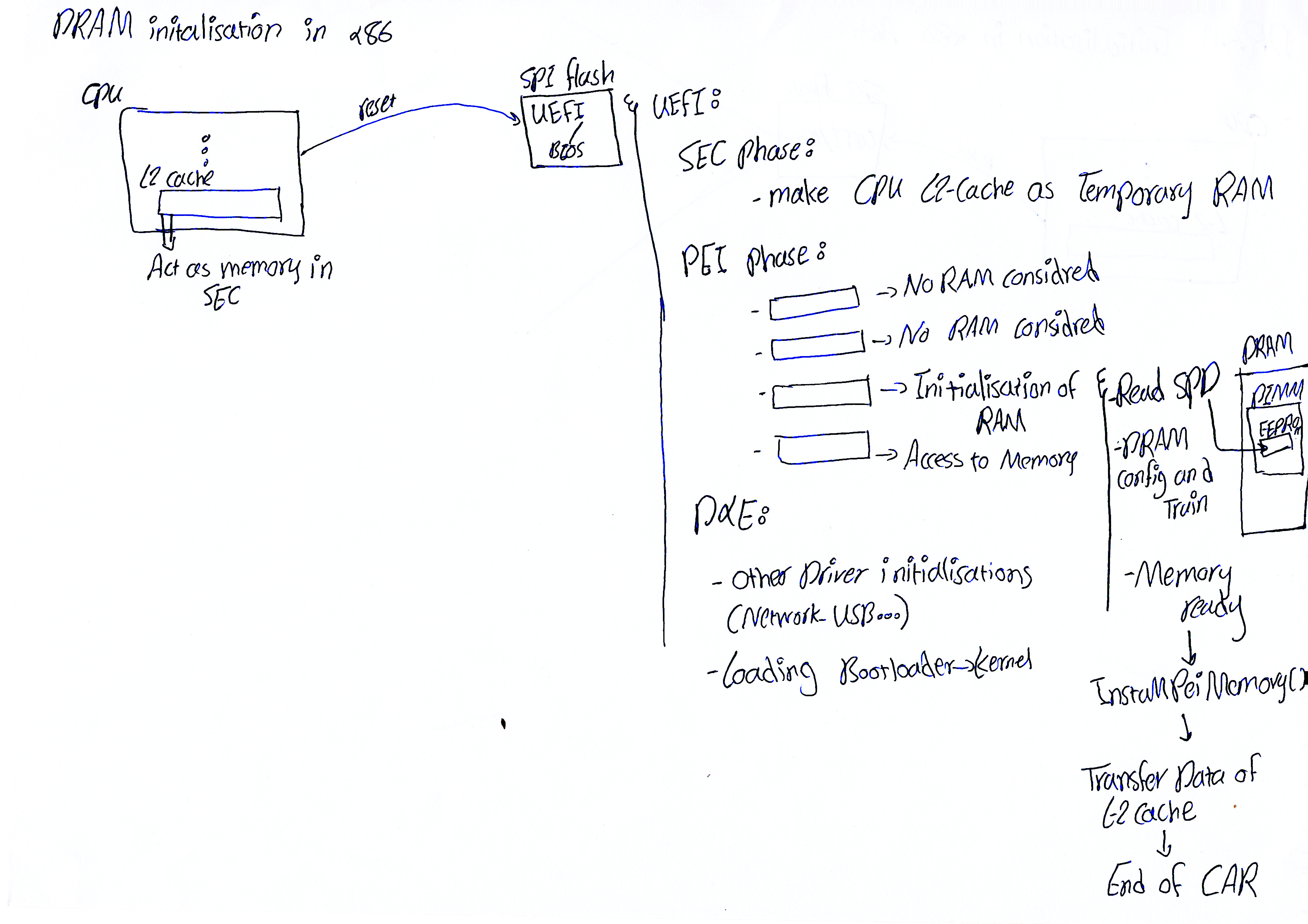
RAM Initialization on x86-64 Systems
Reset Vector and Execute-In-Place
When the processor resets, the CS and IP registers are set up to point to a fixed address on the SPI flash chip that holds the UEFI/BIOS firmware. The processor reads its instructions directly from that flash, without copying anything into RAM first — this is called Execute-In-Place (XIP).
The reason is simple: at this stage, DRAM hasn’t been configured yet. Unlike many embedded systems that have a small block of on-chip SRAM available, most x86 platforms don’t give the firmware anything like that. So at this point there’s no read/write memory at all, which means there’s no stack either. And without a stack, running C code is effectively impossible — every function call and every local variable needs somewhere writable to live.
Cache-as-RAM (CAR)
The workaround is to rely on the processor’s own cache instead of RAM. A region of cache is configured to behave independently rather than as a temporary mirror of memory contents, so it can actually be read from and written to. This technique is known as Cache-as-RAM (CAR), and setting it up is done with a handful of assembly instructions.
SEC Phase
The first phase of UEFI is the SEC (Security) phase. It’s during this phase that the cache is switched into CAR mode, giving the firmware a temporary stack. From this point on, the firmware has a much more complete execution environment to work with.
PEI Phase and Memory Initialization
After SEC comes the PEI (Pre-EFI Initialization) phase. This phase consists of a series of modules called PEIMs, executed in dependency order. DRAM initialization happens here. Until the memory PEIM has finished its job, no other module is allowed to assume real RAM is available.
The motherboard has no built-in knowledge of which memory modules the user installed. Each DIMM (Dual Inline Memory Module) carries a small EEPROM called SPD (Serial Presence Detect). The memory PEIM reads the contents of this EEPROM, typically over SMBus. The SPD data includes things like memory type, capacity, rank count, and standard timing parameters.
Once the firmware knows exactly what kind of memory it’s dealing with, it moves on to actually configuring it. Based on the SPD data, it sets the correct frequency, timings, and voltage on the memory controller, then runs a round of calibration and signal testing — memory training — to make sure the memory operates reliably.
Once this step succeeds, the firmware invokes a service that effectively tells the rest of the system: from this point on, this region of real DRAM can be trusted. Along with that announcement, everything that had been held in CAR is copied over to real DRAM. After this handoff, CAR is no longer needed and gets disabled.
DXE Phase
After the PEI phase, control moves to the next UEFI phase, DXE (Driver Execution Environment). Unlike every phase before it — which ran either from flash or from CAR — this phase runs on the real DRAM that was just prepared. Here, the more complete system drivers (disk, network, USB, etc.) get loaded, and control is eventually handed off to the operating system’s bootloader.
Abbreviations
- XIP — Execute-In-Place
- CAR — Cache-as-RAM
- SEC — Security Phase
- PEI — Pre-EFI Initialization
- PEIM — PEI Module
- DIMM — Dual Inline Memory Module
- SPD — Serial Presence Detect
- DXE — Driver Execution Environment